The authors gratefully acknowledge the assistance of all who.
Transformer power supply and filter experiment.
Power supplies have several com ponets which are at first understood separatly and then they are joined together.
Filters and power supplies introduction a power supply takes alternating current or a c.
This transformer will also be used in the next part of the experiment so leave the connections intact when the present part is finished.
Power transformer 120vac step down to 12vac with the center tapped secondary winding radio shack catalog 273 1365 273 1352 or 273 1511.
L c filters power supply filters.
In other words for a transformer there is no direct electrical connection between the two coil windings thereby giving it the name also of an isolation transformer generally the primary winding of a transformer is connected to the input voltage supply and converts or transforms the electrical power into a magnetic field.
Firstly 220v ac is converted into 12v ac by using simple step down 220v 12v transformer.
Low voltage ac power supply magnet wire is small gauge wire insulated with a thin enamel coating.
This large current may damage the diode and at the same time it causes greater heating of the power transformer resulting in decreased efficiency.
It is intended to be used to make electromagnets because many turns of wire may be wrapped in a relatively small diameter coil.
Household wall socket power plug and cord.
Electrical current into d c.
Power from your electric utility con edison and converts the a c.
Now clear a doubt.
Any gauge of wire will work but 28 gauge is recommended so as to make a coil with as many turns as.
Transformers have been used at powerplants since the inception of alternating current generation a century ago.
Through the reclamation power resources office in denver and via the manuals and standards development program.
Stepping down voltage first step is is scale down the voltage by a step down transformer a step down transformer converts the 220 ac voltage to the lower ac voltage.
T 1000 transformer has four windings.
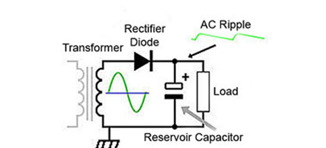
The transformer adjusts the voltage from the ac line to the appropriate voltage and provides isolation.
This transformer is rated at 1 0 kva.
Supplies normally consist of a transformer a rectifier bank and a filter.
Terminal strip with at least three terminals.
The objective of this project is to convert 220v ac supply in to 12v and 12v dc supply that is why it is named dual power supply as we get positive and negative 12v power supply at the same time.
A power supply has been assembled for you and is available from the laboratory tas.
The circuit is shown in figure 1.
There are three step.
Maximum people thinks that a transformer give dc output voltage because we don t get shock by touching its output wire but this is totally wrong.